My New Lazair III

My New Lazair III

Sunday, October 27, 2013

The Wheels of Change on the Bus Go Round and Round, Round and .......


A Wise Man Can Hear Profit in the Wind

Ferengi Rules of Acquisition 22


Busy, Busy, Busy…….There is never enough time in the day.
Many progressive things have come to pass in the few months since my last post. I have acquired a very nice Lazair Series III from Michigan and have been working to get it in airworthy condition. In addition to typical maintenance issues on this bird I have installed a set of 
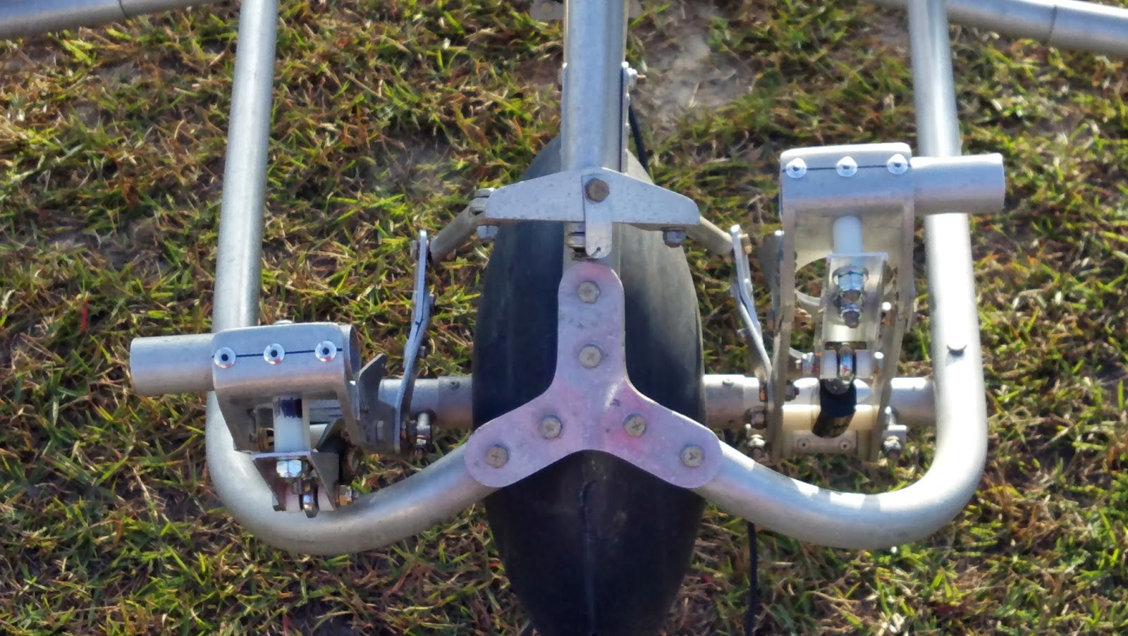
Black Max Brakes and it has much improved ground handling. Have a look at the pics below to see the mods. If anyone is interested I have a complete kit available to do the conversion. Therefore I now have two complete sets of original Lazair wheels and brakes available for sale with nosewheels (rotating skid). These first two pictures are before the brake mod, and after.


The Black Max Wheels give the Old Girl a sporty look don't you think? The extra wide stance reduces side sway when taxiing too.

The brake mod has a small problem, with a very beneficial fix. The master cylinder shaft hits the forward fuselage tube and you lose about 1/2" of rudder pedal movement.


The fix is to add the rudder belcrank extension you see. This extension adds one inch to the rudder pedal throw, increases the total rudder deflection and "speeds up" the rudder pedal movement, i.e. more throw per degree of pedal travel. This is beneficial because the Lazair were always wanting for more rudder authority.


Here are some development pictures of the brake install.


And some photos of the Axle and Caliper installation.


The last pics show the pedal mods needed to get enough throw on the master cylinders. I installed a toe tube on the pedal to give more throw and to widen the brake pedal, I always thought they were too narrow.


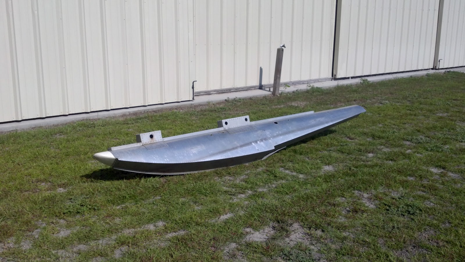
In addition to gaining an extra bird I have been progressing on the Mark IV. I have installed the endcaps on the ailerons, sorry no pics right now. Also I have built a test stand to run-in the Evolution Radials and have run the first one. You can see a poor quality video here:  http://youtu.be/KpmPpXnu5cE. I took this video from my cell phone so it’s not the best but you get a good look at my test stand and hear the engine run. These are real hoss’s for powerplants and are really going to liven up the Mark IV. I have a 32 x 12 Valley View break-in prop on right now and this engine spins the devil out of that thing. I will need to make an external electric starter as hand propping this beast is both dangerous and tiring. Maybe a converted marine outboard starter motor? Taking suggestions on this one.

More Next Time,
Gene
Fltofancy@gmail.com

Wednesday, July 17, 2013


Ailerons and Engines
 
Yanking and banking soon possible
 
If you have good health, consider yourself lucky. I have had some health challenges of late and am far behind schedule, but enough about me.
We have ailerons and engines. Before the doom and gloom set in, and after my last post I made a set of ailerons and they are quite handsome, if I do say so myself. The construction method is somewhat similar to the wing ribs, foam rib cores with sheetmetal capstrips. A 1.5” tube is the spar and a ½” tube for the trailing edge with sheet metal to make a pointy edge. I designed the ailerons on Solidworks and had a full size template printed out. I glued this to a hollow core door to build on, just like my RC modeling days. I made rib locators out of blocks of 2 x 4 and glued them in place. This holds all parts in location and all that is necessary is to drill the rivet holes and pop them in place. The ailerons are very strong in torsion, more so than I expected, without using triangular gussets like on the Lazair. In the pictures the trailing edge sheetmetal is only sitting in place, it is not permanently fastened yet. You can see the end caps, which also are not finished, they need trimming and riveting. A unique aspect of these ailerons is they are symmetric so both LH and RH ailerons can be built on the same jig. To move from one side or the other all you do is install the control horns (not pictured) on the top or bottom of the spar tube to get the alignment to match the aileron control rod, which will exit the top of the wing on the Mark IV.


This symmetric construction required a different pivot setup than the original Lazair. If you will notice the pivot is in the center of the spar tube, via a bushing and stud setup. You will also notice a “pillow block” type bearing on the stud. This gives an illustration of how the aileron pivots. A bearing is installed on the inboard (#6) rib and the outboard tip rib. The inboard stud will float in the bearing. That is it is free to slide inboard/outboard because the stud is considerably longer than need be and will actually penetrate into the inboard rib about an inch, a hole in the rib allows for this by design. The outboard rib will constrain the aileron as it will have a bolt as a stud and will capture the aileron inboard/outboard motion. This end is covered by the wingtip and will not be seen except during maintenance. To install the aileron you will slide the inboard stud into the bearing at an angle until the aileron will fit in the aileron gap of the wing. Lift the aileron into place and align the outboard bearing. Install the bolt and safety. Install the wingtip, connect the aileron control rod, repeat for the other side.


Engines, The Heartbeat of the Bird
I think I posted some time ago that I had intentions of using Hirth F-36 engines on this first Mark IV prototype. However fortune has smiled on me and I have been able to acquire two brand new, in the box, Evolution 7 cylinder 260cc four stroke engines. They are sitting in my closet right now and every now and again I have to open the door to look at the boxes and smile. These engines are an incredible work of art in metal. Check out the website and youtube video links below: 


I expect to be the first ultralight with twin radial engines. Maybe a world record? Probably not but really cool never the less. I am making a test stand to break these engines in. I plan to post videos of them running as soon as possible.
Propellers are a beast of another color and have proven to be more troublesome than you might think. I could certainly get propellers for these engines from the RC world, but I think they look out of place on the Lazair, too thin. The problem of what pitch to use is also problematic. I don’t want to buy a dozen props to figure out which pitch is right, that’s expensive research. I really wanted a ground adjustable prop and in particular a three bladed adjustable prop. After many years of research there was only one choice, Solo Props. 
 
So right now Solo is building two sets of 32” 3-blade adjustable props. Should be ready in the next month or so. They look just like Hamilton-Standard props off a DC-3.


More next time,
Gene

Tuesday, February 19, 2013

RIBS,RIBS, O MY!


Ribs, Ribs Everywhere, and Not a Drop to Drink.

 WE HAVE RIBS!

The second generation ribs are in and they are very nice I must say. See pics below. These ribs are made from rigid polyurethane foam, the same material I tried to cast ribs from. These are made from 1” sheet foam routed to shape and capped with an aluminum capstrip top and bottom. I had to make wood templates by hand from my CAD files so it took some time since the last post. The cap strips are .020” aluminum bent into a “C” channel and then hand fluted and fitted to each rib, then attached to the foam with contact cement, a time consuming process. The ribs are painted, white in this case, with gloss exterior latex paint to protect them from UV damage. This particular rib weighs 13oz, I haven’t weighed an original rib yet but they “feel” about the same. I suspect it is slightly heavier with the paint. These ribs are much stiffer than the original ribs and I have to say I am quite pleased with how they turned out.


Finished Rib


Foam Blank painted with acrylic latex paint

Upper Capstrip, formed to match upper surface contour

Lower capstrip

Upper and Lower Capstrips fastened with two stainless rivets

Closeup

Corner Detail


A youtube video documenting the rib making process is in the works. Perhaps it will be of some help as part of a video construction manual.

I am currently making the sheet metal brackets that attach the ribs to the spar and trailing edge. Complete wings are now within a foreseeable future.
 
 
More Next Time,
Gene
Fltofancy@gmail.com

Monday, November 19, 2012

The Best Laid Plans of Mice and Men……

One of my all-time favorite movies, Randy Quaid did a fantastic job as Lenny, so much so, and as I was quite young when I saw the movie, I thought for years he truly was mentally disabled. And Berretta played his part very well too.


I have made the first rigid polyurethane ribs from my rib mold. The ribs have turned out to be very strong and the foam bonds very well to the aluminum as expected. However there are some aspects to the process I did not anticipate and it looks like I am going to abandon this process.


The foam is much stronger when expanding than first thought. In my research I had been warned that the foam had the ability to exert great pressures against any enclosing structure (probably a uni-directional force as opposed to a true pressure). So I expected the first rib to lift the top plate of the mold and create an overflow between plates. Therefore I put a 20lb weight on the top plate, but alas it wasn’t enough and added an additional 20lbs too late in the cycle to make any difference. Because I didn’t know exactly how much foam to put in the mold it was a big guess on the first pour. I mixed 150ml of A and B, 300ml total on the first pour. The foam lifted the top plate nearly a half an inch. But no big deal as this was just a test anyway and it would give me a good idea of how the foam would stick to the top plates. Once the foam was cured I removed the top plate quite easily. It gave a bit of resistance at first but then popped loose. But O MY! The static electricity it made! Several good zaps before I got it completely off. The overflow had to be chipped away until I reached the Inside Mold Line (IML). However the rib would not slide out of the profile plate even after chipping the overflow from both sides, I had to take a hacksaw blade and very carefully cut it out. After removing the rib the profile plate cleaned up rather easily with a putty knife. The foam doesn’t actually adhere to the HDPE, it appears to be a purely mechanical attachment to the tooling marks left in the material during machining.


I lined the profile plate with a 1” aluminum strip and used 100ml each of the foam components (200ml total) for the second pour. The blue tape is to hold the aluminum strip in place. After mixing the foam and pouring the mix into the profile plate you have to swish it around to cover all the bottom of the mold area, it doesn’t flow well once it is expanding. I quickly put the top plate on and added the 40lbs of weight. I was astonished to see the top plate had lifted about 3/16” when I went to remove the mold. So since this mold still had overflow I had to chip the overflow away up to the aluminum strip. The rib then slipped out of the mold with a bit of persuasion. This second pour could be a viable rib but it is too thick. It turned out exactly as expected, the capstrip is well adhered, the rib is extremely strong and is a third heavier than the original Lazair rib, but is a third thicker too. The new ribs will likely be nearly the same weight as the originals once the thickness is under control.


Several unforeseen difficulties have arisen that threaten this process. The primary one is the foams ability to lift a significant amount of weight while expanding; the second is the relatively small amount of foam necessary to fill the void. The lifting of the foam drives the need to have very accurate amount of foam mix poured in the cavities, coupled with the already small amounts of foam means that for this to be a repeatable manufacturing process the foam mix must be carefully controlled. With already small component volumes this becomes very difficult with equipment at hand. If the foam lifts the mold plate and overflows removing the rib from the mold becomes too labor intensive to be economical and the rib requires extra rework to make it a uniform thickness and meet quality controls. Therefore, unfortunately, I am abandoning this process and looking to a more traditional method for making ribs.


The new method will be to buy the foam pre-expanded to a uniform thickness and route it to profile with a template and flush cut router. The drawback to this method is the foam boards are rather expensive, somewhere on the order of $200.00 in materials for a complete shipset. It may turn out to be a wash when the reduced labor is taken into account, but this means the rib capstrips will have to be bonded in a separate operation. I wonder if JB Weld would work. I’ve already purchased a suitable router table and router. I need to make some templates and order some foam.


In other news I have pictures of the 2SI engines that are for sale. They are 2SI 215F’s with Prince P-Tip Props, you can find info on them on the 2SI website. If interested please contact me. I am also working on a wheel and brake replacement. I am having adaptor bushings machined now and will post pictures as that project progresses.


More Next Time,
Gene
Fltofancy@gmail.com


Saturday, October 13, 2012

Old Rusty Bits for New Shiny Parts


As promised...more updates.
 
As I continue to unpack I make fresh and exciting discoveries on a continuing basis. Along with the tooling that makes the seat bows, I think (and hope) I have discovered tooling that presses the upper and lower channels for the engine pylons. The upper channel was considerably worrisome as it is not easily reproduced without proper tooling and I really didn't want to reinvent the wheel so to speak and develop new tooling, even though  I am in several different areas (like the wheels). Dale's design for these parts was at once elegant and simplistic, always a hallmark for lightweight strong structures. Making a proper press fixture for this part is expensive. The lower channel is relatively easy to make with a hammer and form had we needed. But we have the tooling, it needs some TLC to be sure but at first take appears to be serviceable.


We also found some other punches and tooling and are sorting those out as well.


Progress is being made, slowly but surely. I have to remind myself the hare won the race.


More next time,
Gene
Fltofancy@gmail.com

Monday, September 10, 2012

New Digs


Well I’ve finally jumped off the deep end. I guess the old saying of “Put your money where your mouth is” has come into play. I have leased a small T-hangar at the local (if you call 30 miles away local) grass strip. I am unloading all the tooling for Lazair stuff and trying to figure out what all these old rusty bits do, or used to do. So far I’ve found the tooling used to make the seat bows, a crude but ingenious bit of tomfoolery, and am figuring out how to use it. There are bits and pieces of all sorts. In the discovery we’ve come across a roll of Tedlar, looks to be in good condition after you take a few feet of damaged and aged material off. I’ve found several replaceable propeller blades, perhaps some testing was going on with ground adjustable props? There are 3 Rotax 185’s with Bi-props, and two 2SI engines with Prince P-Tip props. But the crowning jewels, besides a complete Series 3, maybe it’s an Elite airframe, are two absolutely beautiful sheet metal floats for the Lazair, pics below. Whoever made these put a supreme effort in, they are wonderful works of art in aluminum, and very light weight. I don’t have a scale yet but they can’t be more than about 7 lbs each. These were truly a labor of love and craftsmanship par excellence and very labor intensive indeed! As we are not going to offer float options in the foreseeable future we are offering these floats for sale as well as the engines and propellers. There is also a set of original wheels and brakes for sale as well.


Immediately we are going to work on making ribs out of our mold, getting the first set of D-Cells ready with the beefed up spars and fuel tanks in the leading edges, and new landing gear main wheels. Please contact me if you’re interested in any of the parts.
 
As the weather cools off here in south Georgia I will be to working on getting this project up and moving and will post updates more often as we make significant accomplishments. Thanks for taking time to have a look see.


More Later,

Gene

Fltofancy@gmail.com