My New Lazair III

My New Lazair III

Monday, November 19, 2012

The Best Laid Plans of Mice and Men……

One of my all-time favorite movies, Randy Quaid did a fantastic job as Lenny, so much so, and as I was quite young when I saw the movie, I thought for years he truly was mentally disabled. And Berretta played his part very well too.


I have made the first rigid polyurethane ribs from my rib mold. The ribs have turned out to be very strong and the foam bonds very well to the aluminum as expected. However there are some aspects to the process I did not anticipate and it looks like I am going to abandon this process.


The foam is much stronger when expanding than first thought. In my research I had been warned that the foam had the ability to exert great pressures against any enclosing structure (probably a uni-directional force as opposed to a true pressure). So I expected the first rib to lift the top plate of the mold and create an overflow between plates. Therefore I put a 20lb weight on the top plate, but alas it wasn’t enough and added an additional 20lbs too late in the cycle to make any difference. Because I didn’t know exactly how much foam to put in the mold it was a big guess on the first pour. I mixed 150ml of A and B, 300ml total on the first pour. The foam lifted the top plate nearly a half an inch. But no big deal as this was just a test anyway and it would give me a good idea of how the foam would stick to the top plates. Once the foam was cured I removed the top plate quite easily. It gave a bit of resistance at first but then popped loose. But O MY! The static electricity it made! Several good zaps before I got it completely off. The overflow had to be chipped away until I reached the Inside Mold Line (IML). However the rib would not slide out of the profile plate even after chipping the overflow from both sides, I had to take a hacksaw blade and very carefully cut it out. After removing the rib the profile plate cleaned up rather easily with a putty knife. The foam doesn’t actually adhere to the HDPE, it appears to be a purely mechanical attachment to the tooling marks left in the material during machining.


I lined the profile plate with a 1” aluminum strip and used 100ml each of the foam components (200ml total) for the second pour. The blue tape is to hold the aluminum strip in place. After mixing the foam and pouring the mix into the profile plate you have to swish it around to cover all the bottom of the mold area, it doesn’t flow well once it is expanding. I quickly put the top plate on and added the 40lbs of weight. I was astonished to see the top plate had lifted about 3/16” when I went to remove the mold. So since this mold still had overflow I had to chip the overflow away up to the aluminum strip. The rib then slipped out of the mold with a bit of persuasion. This second pour could be a viable rib but it is too thick. It turned out exactly as expected, the capstrip is well adhered, the rib is extremely strong and is a third heavier than the original Lazair rib, but is a third thicker too. The new ribs will likely be nearly the same weight as the originals once the thickness is under control.


Several unforeseen difficulties have arisen that threaten this process. The primary one is the foams ability to lift a significant amount of weight while expanding; the second is the relatively small amount of foam necessary to fill the void. The lifting of the foam drives the need to have very accurate amount of foam mix poured in the cavities, coupled with the already small amounts of foam means that for this to be a repeatable manufacturing process the foam mix must be carefully controlled. With already small component volumes this becomes very difficult with equipment at hand. If the foam lifts the mold plate and overflows removing the rib from the mold becomes too labor intensive to be economical and the rib requires extra rework to make it a uniform thickness and meet quality controls. Therefore, unfortunately, I am abandoning this process and looking to a more traditional method for making ribs.


The new method will be to buy the foam pre-expanded to a uniform thickness and route it to profile with a template and flush cut router. The drawback to this method is the foam boards are rather expensive, somewhere on the order of $200.00 in materials for a complete shipset. It may turn out to be a wash when the reduced labor is taken into account, but this means the rib capstrips will have to be bonded in a separate operation. I wonder if JB Weld would work. I’ve already purchased a suitable router table and router. I need to make some templates and order some foam.


In other news I have pictures of the 2SI engines that are for sale. They are 2SI 215F’s with Prince P-Tip Props, you can find info on them on the 2SI website. If interested please contact me. I am also working on a wheel and brake replacement. I am having adaptor bushings machined now and will post pictures as that project progresses.


More Next Time,
Gene
Fltofancy@gmail.com


Saturday, October 13, 2012

Old Rusty Bits for New Shiny Parts


As promised...more updates.
 
As I continue to unpack I make fresh and exciting discoveries on a continuing basis. Along with the tooling that makes the seat bows, I think (and hope) I have discovered tooling that presses the upper and lower channels for the engine pylons. The upper channel was considerably worrisome as it is not easily reproduced without proper tooling and I really didn't want to reinvent the wheel so to speak and develop new tooling, even though  I am in several different areas (like the wheels). Dale's design for these parts was at once elegant and simplistic, always a hallmark for lightweight strong structures. Making a proper press fixture for this part is expensive. The lower channel is relatively easy to make with a hammer and form had we needed. But we have the tooling, it needs some TLC to be sure but at first take appears to be serviceable.


We also found some other punches and tooling and are sorting those out as well.


Progress is being made, slowly but surely. I have to remind myself the hare won the race.


More next time,
Gene
Fltofancy@gmail.com

Monday, September 10, 2012

New Digs


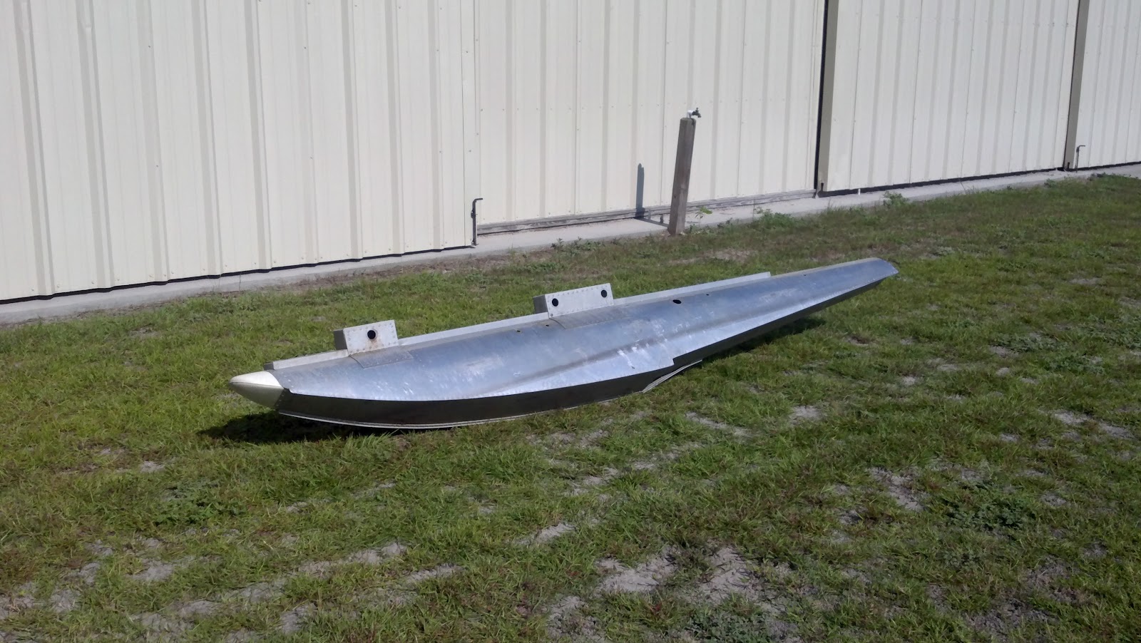
Well I’ve finally jumped off the deep end. I guess the old saying of “Put your money where your mouth is” has come into play. I have leased a small T-hangar at the local (if you call 30 miles away local) grass strip. I am unloading all the tooling for Lazair stuff and trying to figure out what all these old rusty bits do, or used to do. So far I’ve found the tooling used to make the seat bows, a crude but ingenious bit of tomfoolery, and am figuring out how to use it. There are bits and pieces of all sorts. In the discovery we’ve come across a roll of Tedlar, looks to be in good condition after you take a few feet of damaged and aged material off. I’ve found several replaceable propeller blades, perhaps some testing was going on with ground adjustable props? There are 3 Rotax 185’s with Bi-props, and two 2SI engines with Prince P-Tip props. But the crowning jewels, besides a complete Series 3, maybe it’s an Elite airframe, are two absolutely beautiful sheet metal floats for the Lazair, pics below. Whoever made these put a supreme effort in, they are wonderful works of art in aluminum, and very light weight. I don’t have a scale yet but they can’t be more than about 7 lbs each. These were truly a labor of love and craftsmanship par excellence and very labor intensive indeed! As we are not going to offer float options in the foreseeable future we are offering these floats for sale as well as the engines and propellers. There is also a set of original wheels and brakes for sale as well.


Immediately we are going to work on making ribs out of our mold, getting the first set of D-Cells ready with the beefed up spars and fuel tanks in the leading edges, and new landing gear main wheels. Please contact me if you’re interested in any of the parts.
 
As the weather cools off here in south Georgia I will be to working on getting this project up and moving and will post updates more often as we make significant accomplishments. Thanks for taking time to have a look see.


More Later,

Gene

Fltofancy@gmail.com

Friday, July 13, 2012

A Lifetime Doesn’t Seem Like Enough

While it is never my intention to use this forum as a vehicle to air out my personal life, I have noticed 5 months have gone by since my last post and there have been a small but steady stream of people repeatedly visiting the site from all over the world. This indicates there is some number of folks still interested in my little slice of heaven. So to those watching I have not been slacking off. Between February 27 and April 6 I lost 3 very important members of my family (Grandmother, Mother, and Father) all two weeks apart like clockwork. And although their deaths were not related; one has to wonder, given their life stories, if their fates were not somehow connected. But that is a story for another time. 


As you may imagine these events have taken a heavy toll emotionally and spiritually, and honestly I just haven’t had the gumption to work on the Lazair project lately. But it is time to put that behind me and get going once again. While I don’t have anything noteworthy to post just yet, I wanted to take a moment and thank those folks all over the globe that have checked in to see if something new had been put up. The steady tick of the visit counter has inspired me and warmed my heart to know that there are a few people in the world that would still be interested in what I am doing even after months of silence, and to those people I say thank you. 

More to come very soon,
Gene

Monday, February 6, 2012

More on Fuel Tanks


One Down, One to Go

Another Town and One More Show…..


Those of you who are fans of eighties music will get that reference.

This update is twofold; one fuel tank is finished and we have pictures with a piece of leading edge skin to show the fuel filler neck installation, and we have our first rib mold. 

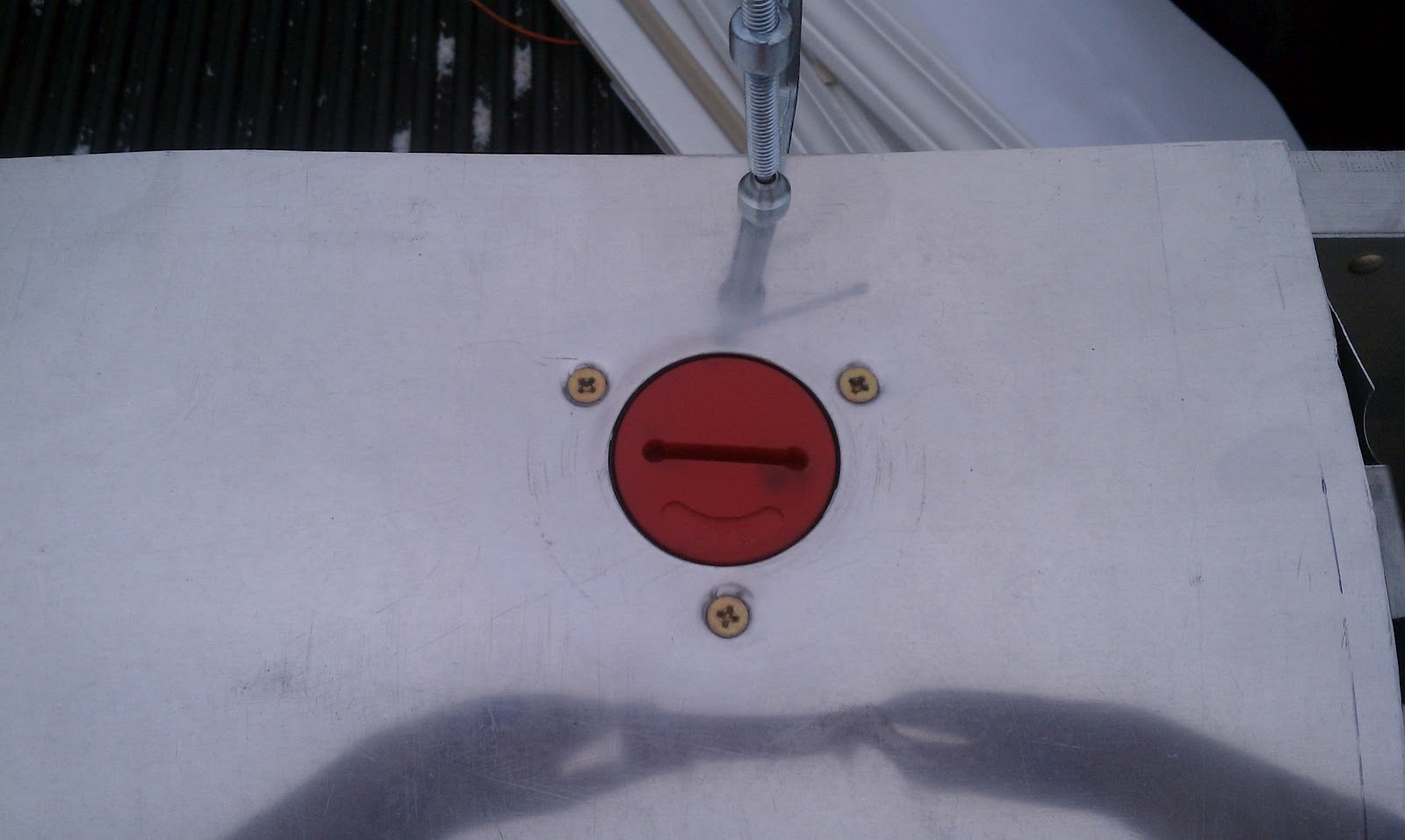
This first picture shows a top view of the fuel filler neck we have selected. It is a glass filled nylon unit with a nice red screw on cap. As you can see in the pictures it is fitted from beneath the leading edge skin so just the filler cap is visible. It is a nice flush install; the cap is domed and sticks up above the skin just slightly. All in all a fine solution to the filler neck problem. These necks are lightweight and low cost, all pluses in this application. If a customer wanted a polished leading edge we can swap out the red cap with a polished stainless steel cap.


The next picture illustrates the filler neck installation from inside the D-Cell. The screws are obviously too long and will be replaced with stainless screws of the proper length at the final installation. The white corrugated tubing is nylon marine bilge pump tubing, really great stuff, gasoline resistant and flexible. The tubing is sealed to the filler neck with gas proof sealant and held in place with a screw (not visible in photo). This installation has been leak tested and everything is good to go.


The last pictures show a more detailed view of the gas tank construction than the last blog. The outboard cap has a nylon fitting installed for the filler neck and tubing to attach to. 

The inboard picture shows the vent tubing and fitting at the top of the tank and the fuel outlet fitting, tubing, and primer pump/check valve with tubing going to the center cross-over and to the engine.


The following pictures show our beautiful new CNC cut rib mold. It is 1” HDPE machined to the rib profile. The second and third pictures show an original Lazair rib fitted into the mold. It is a nice tight fit just like it should be. 


The premise of the mold is to line the profile with aluminum capstrips and cast the mold with 2 lb/cu ft rigid polyurethane expanding foam, let it set up and pop the new rib out of the mold. The polyurethane foam will adhere to the aluminum capstrip tenaciously, and the foam is chemical resistant (including gasoline) and is considerably stronger than the original polystyrene (Styrofoam) ribs. This is a quick, easy way to make ribs and they will all be exactly the same each time. I’ll do another post when we cast the first rib…stay tuned.


More Next Time,
Gene
Fltofancy@gmail.com

Friday, October 28, 2011

Fuel tanks - And their complications

I've been working on the fuel tanks and their installation on the Mark IV Prototype recently and thought I might share some of the thoughts and doctrine that went into their design and some practical challenges in what might be considered a relatively simple system. The decision to relocate the fuel tank(s) into the wing leading edges is discussed in the previous blog so I won’t go over that again. This blog is more about how to make that decision a reality.


Gasoline, and more particularly current day ethanol mixed gasoline, is a tricky chemical concoction to handle and even more so in an aircraft application, as opposed to a marine or automotive installation, it eats pretty much anything it touches especially rubber. Airplanes have a history of causing peculiar things to happen to both the gas and the tanks it is stored in, not to mention the compounding problem of what happens if you have fuel starvation. The initial problem to solve is how to store the gas on board, a gas tank of course. This is not a real problem if you have a budget to have custom rotomolds made for rotomolding nice polyethylene tanks, not an option at this point in the program. Where to get an affordable gas resistant material in the shape of a cylinder to fit inside the circular openings of the leading edge ribs? Literally a couple of years and hundreds of hours of research later the local hardware store had the answer all along. Polyvinyl Chloride pipe is gasoline AND ethanol resistant, I can make fuel tanks from PVC pipe! Inexpensive, lightweight, and it works. OK so I was skeptical about PVC standing up to gasoline just like you, so I did a practical test. I bought a small PVC fitting and immersed it in a container of 90/10 gasohol (same stuff you get at the pump everywhere) with 2-stroke oil mix. I let it sit for 30 days on continuous immersion. When the fitting was removed there was no, REPEAT NO discernable degradation in the material. It was not soft, or swollen, or hard, or brittle. As a matter of fact I wiped it off with a towel and noted only a very minor tint from the 2 stroke oil and after letting it dry overnight the tint faded and there wasn't even a hint of gasoline odor. I still wasn't convinced. I made a test tank with all the baffles and cemented joints and brass fittings and yada, yada, yada. I filled the tank about half full and let it sit for 30 days. At the end of the test I drained the fuel, no noticeable change in the gas; it ran fine in my weed eater. I cut the tank open and there was no degradation of the joints or any other PVC parts. I think this is a good material to make fuel tanks with. Still it will be recommended to drain the tanks for extended storage.


The next concern is installation. The leading edge ribs are very thin and will surely cut into the tanks from vibration if left unprotected, and there is the complication of how do you feed two engines off two tanks simultaneously and continually when one tank could un-port in an uncoordinated or prolonged turn. Protecting the tanks is easily accomplished with some corrugated split conduit available everywhere and some judicial clamping.

PVC fuel tank installation in leading edge ribs, tubing seen is not completely installed or plumbed, but illustrates plumbing routing. Small line on top is fuel tank vent, lower is main fuel line run to engine position


Close up of fuel tank installation showing conduit protection from sheetmetal ribs


 The plumbing problem however, persisted for quite some time. I didn't want to complicate the operation by installing valves to feed both engines off one tank at a time, this has caused many a fuel starvation problem in "real" airplanes and still causes problems today on airplanes with multiple tanks. I didn't want to isolate the tanks one to each engine, I wanted both engines to have access to both tanks all the time. After a bit of brain picking I came up with a solution, and a clever one I think. Hydrodynamics says that if two tanks are plumbed together and exit via one route the tank with the highest hydrodynamic pressure (head) will always feed (empty) first. If we consider the Lazair in a turn (bank) one tank will be higher than the other (i.e. one wing high, one wing low with respect to the center line of the craft) therefore that higher tank will feed, and in the case of an uncoordinated turn the lower tank will un-port, that is fuel will run away from the outlet. But the higher tank will also feed into the lower tank, an unwanted situation. How to control the cross feed into the lower tank while supplying both engines with adequate fuel? Check valves to the rescue!! Check valves like I need are unavailable; believe me I looked high and low. But sometimes the most obvious answers can’t be seen until they hit you right across the head, or fall into your shopping cart at Wal-Mart. Inline Marine fuel bulbs that are used to prime the outboard engine are PERFECT check valves for this installation. They come in the right tube sizes (3/8”), they are alcohol resistant (an arguable point because the ones I use on my boat get hard after about a year or so), and they will provide a means to prime the engines (probably not necessary with the pumper carbs and the gas so close). So the fuel is routed thusly: both tanks output to a fuel bulb and then to a common tee, this tee is routed to another tee that feeds both engines. A diagram would really be helpful right about now.


Fuel bulb shown for reference only, not hooked up yet, no fittings installed in tank yet


That solves the fuel delivery issues, and the beauty of the system is it is self-leveling. The highest tank will always feed until both tanks are equal, and the tanks will swap out automatically as the ultralight banks and levels in flight.
The only problem to overcome now is un-porting and filling issues. Un-porting is handled by internal baffles in the tanks. I considered fuel tank foam, like they use in race cars, although an elegant an ultimately effective solution, alas again too expensive.  I designed baffles from .020” thick aluminum sheet metal that is sandwiched in place inside the tank with two rings made from thick walled PVC tubing with a small section removed and cemented into place as to make a retainer of sorts, and holes in proper places to allow fuel to run out the bottom and air to vent at the top. There are three baffles in each tank, one on the outboard third, one about halfway and one near the inboard tank outlet. The thought is that each section will hold a certain amount of fuel for a certain amount of time until it drains into the adjoining section.

Inside of fuel tank showing metal baffle, retaining ring and holes for fuel flow and venting


So the high tank is always feeding to the drain port and to the engines and the low tank will have some fuel retained in the inboard and middle sections closest to the drain port so as to not allow all of the fuel to run to the low end. This also reduces the tendency for either wing to become out of balance because fuel has run to the outboard end of the tank, as in a prolonged bank (i.e. turns around a point). The tank fill ports are still somewhat a work in progress. I have several options to consider, and perhaps the best one is again derived from the marine world. Boat shops have many, very nice deck fill options including a black plastic deck fill and a polished stainless steel deck fill, either of which would make excellent exterior fuel filler necks, but one is a bit cheap looking and the other, although reasonably affordable, weighs a ton.

Possible tank filler neck

Possible tank filler neck


I am also looking at an internal fill option that would hide the filler neck inside the leading edge and would be accessed via a hatch on the leading edge. What would the market prefer? Comments welcomed.     

More Next Time,
Gene
Fltofancy@gmail.com

Friday, October 7, 2011

Blogging - The new telephone call?

First Lazair Nouveou Blog

So I'm very new to this blogging thing.

This site will be a tool to communicate news and info about Lazair Nouveou and the journey of resurrecting the famous Lazair ultralight.

Where to start - where to start......

The Lazair project is moving at an incredibly slow pace. Although some things are happening, any visible progress is invisible. We have obtained all the tooling, what there was of it, from Michigan (October 2010), and we have all the necessary rights and licenses in place to sell under the Lazair name (HUGE sales importance). We have been capturing the Lazair design in Solidworks (parametric 3D CAD software), and are updating a few items to take advantage of modern manufacturing techniques and materials. The end product will appear to be exactly like the Elite or Series III Lazairs, however there are several major differences; strengthened wing spars (for 350lb pilot), different main landing gear wheels and nosewheel with better brakes, relocated fuel tank (from behind seat to inside leading edge D-cells), Hirth F-36 engines, BRS recovery parachute, and rigid polyurethane foam for the wing ribs. It will be named the "Mark IV".

Design Issues
Ultraflight released very few drawings for parts (only tubes) to the public, there is some debate as to how much of the design was captured. In making Solidworks models of the Lazair parts everything is pretty straight forward and simple to model, although very time consuming to reverse engineer, except for the wing ribs. I asked Dale how he designed the rib profiles, his answer was he hand lofted them using parts of other ribs he was familiar with and developing the lines until they were pleasing to his eye. Very creative and yet another indicator of his natural ability as an aircraft designer. However this becomes a nightmare when trying to model the ribs in 3D CAD. So I had a couple of choices; I could simply model something that looked OK but wasnt really representative of the real airfoils, and therefore couldnt be used as a base for modern CNC manufacturing techniques to make templates, I could send the ribs out and have them Z-scanned and a point cloud for each developed and make models from that (really cool technology, but very expensive), or I could trace out each rib and graphically extract coordinates and get some useable data to start from (the old school method). I chose the latter course ( I never knew how important those kindergarten tracing lessons were going to be). I created large graph paper and layed each rib down and traced the profile. I then took a 6 inch scale and hand computed each coordinate in half inch increments. A labor of love to be certain, but when finished, a few months later, I had something that no one else on earth has, not even Dale, Lazair rib coordinates. I loaded the coordinates into my CAD software and "wah-lah" I had 3D models of the ribs. After some adjusting and smoothing for measurement inaccuracies I now have beautiful rib models that I can send out and get templates made (molds actually, explanation below).

Why move the fuel tank, and why that drives new rib material and the need for accurate rib models.
The decision to relocate the fuel tank is twofold. Firstly the traditional location is a pain in the back to refuel (literally), you either have to remove the fuel tank (which means lifting it back into the holder when its full of fuel ~30lbs), or contorting your self and holding a gas can at an awkward angle to refill, both of which are extremely hard on your back. Some folks developed special hoses and other things to make the job easier, but this means you have to take that stuff with you if you plan on refueling off your home field. The other reason is to reduce the total lift height from the fuel tank to the carburetors. Although a good pumper diaphragm carburetor will lift the fuel, any small leakage in the fuel line, primer bulb, or joint in the fuel line will cause fuel starvation. It was a significant problem as evidenced by the Lettair Service bulletins. Relocating the fuel tank to the leading edges makes it much easier to access and refuel and drastically reduces the lift height from nearly 24" to about 6" max. But what happens when gasoline is spilled into the leading edge when refueling? This is a major concern and has many facets to overcome. The largest problem to overcome is the fact that gasoline will melt polystyrene (i.e. the blue foam the original ribs were made from), and it could have and adverse effect on the tapes used to hold the covering material on. The design changes to overcome these obstacle are rigid polyurethane foam for the rib material, this is an excellent substitute for polystyrene, and scuppers near the fuel inlet to capture and absorb any spilled gas before it gets to the tapes. Polyurethane foam has the same density as polystyrene and is rigid. Polystyrene is semi-rigid but has very low compression strength. Polyurethane foam is inert to all chemicals, but is not UV resistant (easily overcome with a coat of ordinary inexpensive latex housepaint). Fabricating ribs from 2 lb density polyurethane foam was a bit of a head scratcher to overcome. Polyurethane foam boards in 1" thickness are available, but not locally and they are quite expensive. Looking around for a solution found expanding foam (often referred to as A/B foam) and is quite readily available and affordable from the marine industry. So a plan to cast the ribs from expanding foam was hatched, but to cast something you need a mold. I couldve just got a 1" thick board and made female molds by simply tracing the originl rib profiles, but that just didnt cut in my world. I wanted ribs that were accurate to the original Lazair ribs, but were repeatable if I ever needed to make new molds. So right now shiny new HDPE molds are being CNC cut from the hard work that was put into capturing the rib profiles in CAD and new polyurethane Lazair ribs will be available soon.

Whats the hold up? When will we have new Lazairs rolling off the assembly line?
This is the question I am asked all the time when someone gets wind of what I'm up to. And the answer is.....I wish I knew. I have basically everything needed to make new Lazair parts and whole ultralights except for a place to work in. My little town of Brooklet, Georgia and the larger Statesboro area has few offerings of spaces large enough to set up shop in, and what is available is priced far out of my meager budget. I am still vigilant looking for shop space, but until something comes along I will keep plugging away in the garage.

There will be more to come on the Blogspot page as I get used to this means of communication, check back from time to time. Until then email me at Fltofancy@gmail.com.

Later,
Gene